TL;DR: Sizing a control valve in CONVAL 12 follows the order of the module's own navigation: define the medium and its state, enter the operating point, let CONVAL fill in the fluid properties, describe the pipeline either side of the valve, then configure the valve and read the result. The software applies IEC 60534 for you and reports what matters in the Overview pane: the flow state, the flow type, the required Kv, the stroke position, the predicted sound pressure level and the reliability index. You size to the duty; CONVAL tells you whether that duty is survivable.
Work in the order CONVAL presents
The control valve module lists its sections down the left-hand side, and they are in the order the calculation needs them: Medium, Pipeline, Control valve, Noise calculation, Resistance structures and Control optimization. Working top to bottom is not just tidy. Each section feeds the next, and a valve selected before the pipeline is described will be sized against the wrong velocities.
The worked example below is a water service: 130 °C, 12 bar(a) upstream, 8 bar(a) downstream.
Step 1: Medium selection and state
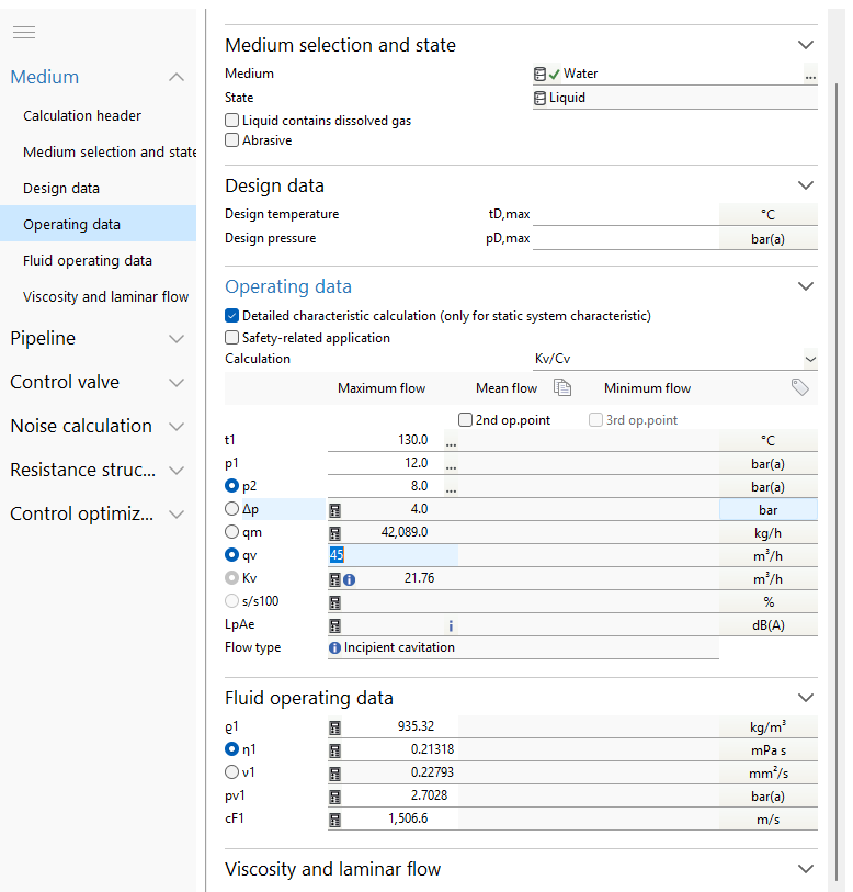
Under Medium selection and state you choose the medium and its state, in this case Water and Liquid. Two checkboxes sit beneath: Liquid contains dissolved gas and Abrasive. Neither is cosmetic. Dissolved gas changes how the fluid behaves as pressure falls towards the vapour pressure, and flagging an abrasive service affects the trim and material guidance you get later.
Design data takes the design temperature and pressure, tD,max and pD,max. These are the vessel or line design conditions, not the operating point, and they are used for the mechanical checks rather than the flow calculation.
Step 2: The operating point
The Operating data section is where the duty is defined. CONVAL gives three columns, Maximum flow, Mean flow and Minimum flow, with optional second and third operating points. Filling in more than one is the single most useful habit in the whole module: a valve that behaves well at design flow can be badly behaved at turndown, and you will not see it from one column.
Set the Calculation mode (Kv/Cv) and enter the operating point:
| Field | Symbol | Example |
|---|---|---|
| Operating temperature | t1 | 130.0 °C |
| Pressure upstream of valve | p1 | 12.0 bar(a) |
| Pressure downstream of valve | p2 | 8.0 bar(a) |
| Pressure difference | Δp | 4.0 bar |
| Mass flow rate | qm | 42,089.0 kg/h |
| Volume flow rate | qv | 45.0 m³/h |
Note the radio buttons beside the fields. They tell CONVAL which value you are fixing and which you want calculated. Fix the flow and the pressures, and the software returns the Kv, here 21.76 m³/h. Fix the Kv instead and it will work back the other way. The remaining outputs in this section, s/s100 (the stroke or angle-of-rotation ratio), LpAe (the A-weighted sound pressure level) and Flow type, populate once a valve is selected.
Pressures are absolute. The fields are labelled bar(a) for a reason. Entering gauge pressures here is the most common way to get a confidently wrong answer, because the margin to vapour pressure is then wrong by one atmosphere and the cavitation verdict flips.
Step 3: Fluid operating data, filled in for you
Once the medium and operating point are set, CONVAL populates Fluid operating data from its own property database. For the example above:
- ϵ1, operating density: 935.32 kg/m³
- η1, dynamic viscosity: 0.21318 mPa s
- ν1, kinematic viscosity: 0.22793 mm²/s
- pv1, vapour pressure: 2.7028 bar(a)
- cF1, speed of sound in the fluid: 1,506.6 m/s
This is one of the quiet strengths of working in CONVAL rather than a spreadsheet. The vapour pressure that decides the cavitation result, and the density that drives the velocities, come from the property database at your stated temperature and pressure, not from a value someone typed in once and never revisited.

Step 4: The pipeline either side of the valve
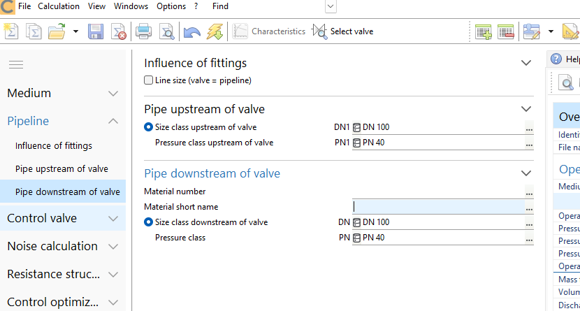
The Pipeline section carries a checkbox at the top, Line size (valve = pipeline). Leave it unticked whenever the valve is smaller than the line, which is most of the time. Ticking it tells CONVAL the valve matches the pipe, and the fitting effects and velocity results change accordingly.
Then describe the pipe each side, because they can differ:
- Pipe upstream of valve: size class DN1 (DN 100 in the example) and pressure class PN1 (PN 40)
- Pipe downstream of valve: size class DN and pressure class PN, with optional material number and short name
This is what allows CONVAL to report u2P, the flow velocity in the pipe, as distinct from the velocity in the valve itself. Erosion and noise complaints are frequently a pipe velocity problem rather than a valve problem, and the two numbers are reported separately for exactly that reason.
Step 5: Configure the valve
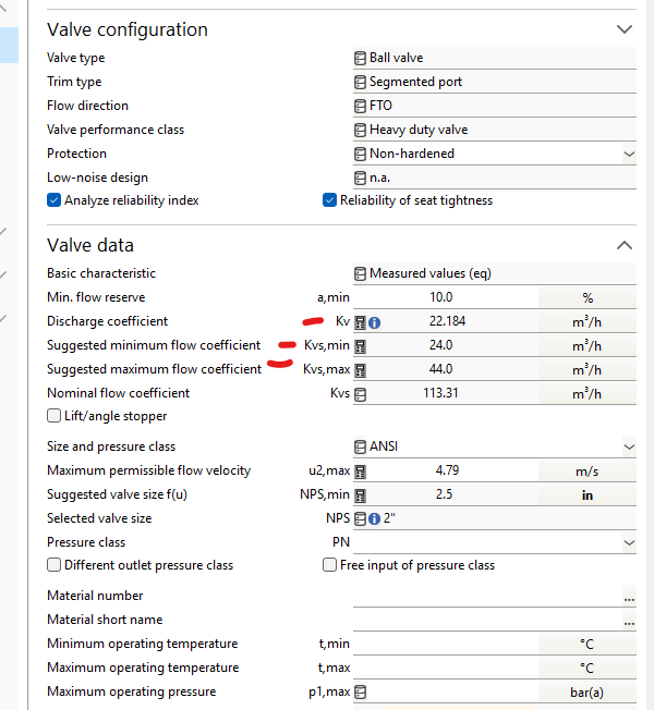
The Control valve section splits into the valve's configuration and its data. Under configuration you set the Valve type (straight globe, ball, butterfly and so on), the Trim type (a contoured plug, a segmented port), the Flow direction, the Valve performance class, whether the trim is hardened under Protection, and whether a Low-noise design applies.
Two checkboxes here are worth ticking as a matter of routine: Analyze reliability index and Reliability of seat tightness. The first is what produces the Ri figure discussed below, and it is the difference between a sizing calculation and a fit-for-purpose assessment.
Under Valve data, CONVAL turns the required Kv into a valve selection:
- a,min, the minimum flow reserve, expressed as a percentage (10% in the example)
- Kv, the discharge coefficient the duty demands, about 22 m³/h here
- Kvs,min and Kvs,max, the suggested minimum and maximum flow coefficients, 24.0 and 44.0 in this case
- Kvs, the nominal flow coefficient of the valve you actually choose
- u2,max, the maximum permissible flow velocity
- NPS,min, the suggested valve size as a function of velocity, and NPS, the size you select
The Kvs,min and Kvs,max pair is the part people skip. It is not a formality: it is CONVAL telling you the window within which the valve will still control. A valve with a Kvs far above Kvs,max will spend its life barely open, and the stroke figure will say so.
Step 6: Read the result, not just the Kv
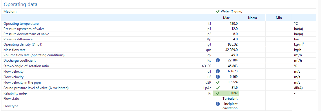
The Overview pane gathers the verdict in one place, and the Kv is the least interesting number on it. What matters:
- Flow state: turbulent or laminar. Laminar flow invokes a different correction and is a flag that the sizing is unusual.
- Flow type: this is the cavitation verdict. In the example it reads Incipient cavitation. It may also report non-choked flow, or choked flow, at which point the valve passes no more flow however much further you drop the downstream pressure.
- s/s100: the stroke or angle-of-rotation ratio. Somewhere near the middle of travel is healthy. Very low means an oversized valve throttling near the seat, which is where trim damage and poor control live.
- LpAe: the predicted A-weighted sound pressure level, to compare against the site limit.
- u2P: the pipe velocity, separate from the valve velocity.
- Ri and Ri,tot: the reliability index for the operating point and for the selection overall. This is the number that turns a valid calculation into an engineering judgement, and it is flagged with a warning symbol when it needs attention.
What CONVAL does with IEC 60534 on your behalf
CONVAL calculates control valves to IEC 60534-2-1, with the noise prediction to IEC 60534-8-3 and 8-4. The standard contains a set of correction factors for pressure recovery, choked flow, the critical pressure ratio and, for compressible service, gas expansion. These are applied inside the calculation; they are not fields you fill in.
That distinction matters more than it sounds. If you go hunting the interface for every symbol printed in the standard you will not find them, because CONVAL's job is to take the operating point, the fluid properties and the valve data you have supplied and apply the standard to them. What you interact with are the inputs above and the results in the Overview pane. What you should check is the outcome: the flow type, the reliability index and the stroke position.
The same workflow covers gas, steam and two-phase service by changing the medium and its state. The sections and the order do not change.
Two pitfalls worth knowing
Gauge instead of absolute. The pressure fields are bar(a). Entering gauge values for p1, p2 or a manually set vapour pressure produces a systematic error in the margin to vapour pressure, and a cavitation verdict that is confidently wrong in either direction.
Sizing on one operating point. A valve sized only at maximum flow can sit almost closed at minimum flow. Fill in the minimum and mean flow columns, or add a second operating point, and read s/s100 and the flow type at each. Most of the value in the module is in the comparison, not the single answer.
References
- F.I.R.S.T. GmbH (2024) CONVAL® 12: control valve module. Product documentation, F.I.R.S.T. GmbH.
- F.I.R.S.T. GmbH (2023) Standards Used in CONVAL 12, November 2023. Available from the CONVAL 12 installation pack.
- IEC 60534-2-1, Industrial-process control valves: Flow capacity, sizing equations for fluid flow under installed conditions. International Electrotechnical Commission.
- IEC 60534-8-3 and IEC 60534-8-4, Industrial-process control valves: Noise considerations. International Electrotechnical Commission.