MHCOS
Multi-Hole Compact Orifice STEAM flow meters measure the flow of saturated and superheated steam within the process industries, including chemical, petro-chemical, pharmaceutical and the power industry. This is especially designed for installations with limited space due to the flow conditioning effect created by the 4 hole design. The meter is based on the principle of measuring velocity in the pipe line, therefore the flow measurement is volumetric. The flow meters are based on international standards and private information covering flow calculation, manufacturing tolerances, accuracy and installation requirements. This new type of bare bone technology enlarge the number of potential successful applications for DP flow meters in world.
The MHCOS flow meter features are:
- Very short straight pipe run requirement
- Standardised product based on well proven technology.
- Compact design.
- Simple construction.
- Standardised construction means low inventory.
- No moving parts.
- Not sensitive to vibrations.
- The electronics delivers linear to flow output signal.
- Digital indicator for local flow reading.
- High accuracy.
- Wide rangeability.
- Easy to install.
- Easy to re-calibrate.
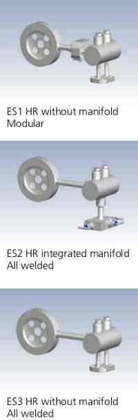
- Models with integrated manifold valve
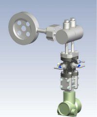
Construction
Model MHCOS
The MHCOS flow meter model consists of a primary element based on the differential pressure principle, an all welded integrated construction, with transmitter mounting flange, 3 of 5 valve manifold and an electronic differential pressure transmitter.
The MHCOS flow meter is mounted between flanges in sizes from DN 40 (11⁄2") to DN 400 (16") in pressure ratings up to PN 40 (300 lbs).
Accessories
Remote electronic indicator with LCD is available for local flow indication and if required check/change of flow rate (differential pressure).
Principle of Measurement
The MHCOS is a velocity flow meter. A restriction in a pipe line changes the value of the different energies. Based on the law of energy balance developed by Bernoulli the sum of energies remains constant. Increases the velocity in the pipe line decreases the pressure in the restriction. The pressure differential between the inlet pressure and the pressure in the restriction is measured expressing the flow velocity. When the physical values of the fluid is known and the inner pipe diameter is established the electronics calculate the flow rate. The flow rate is expressed in an analogue signal 4 - 20 mA or signal for digital communication.
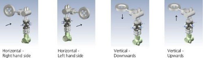
Installation Orientation
Technical Data
- Sizes : DN 50 - DN 400, 2" - 16", larger sizes on request
- Pressure rating : up to PN 40, 300 lbs, higher pressure ratings on request
- Temperature : Process : up to 400°C,
- Mounting style : Between flanges according to DIN or ANSI standards
- Flange facing : flat face (standard), raised face, DIN 2512 N, DIN 2513 R
- Overall length : 32 mm
- Material : Stainless steel AISI 316
- Design and calculation standards : ISO 5167, ASME MFC-3M.
- Drain hole : On request
- β (d/D) : 0,5 and 0,6
- Accuracy : +/- 1,2 %
- Rangeability : 8:1
- Repeatability : better than 0,1 %
- Pressure loss : typical 150 mbar (values are given at full flow)
- Reynolds No : Re > 5000
- Allowable differential Pressure : max 2,5 bar
- Output signal : analogue 4 - 20 mA or Digital communication via protocol, HART, PROFIBUS, Foundation Fieldbus or others.
- Local indicator (option) : LCD showing flowing units or %
- Power supply : 14 - 36 Vdc, typical 24 Vdc.
- Max load (24 Vdc) : 700 Ohm
- Enclosure : IP 67
- Ex protection : intrinsically safe EEx ia IIC T6, Explosion proof EEx d IIC T6
- Temperature : Ambient : -40 - +80°C
Sizes
DIN Flanges
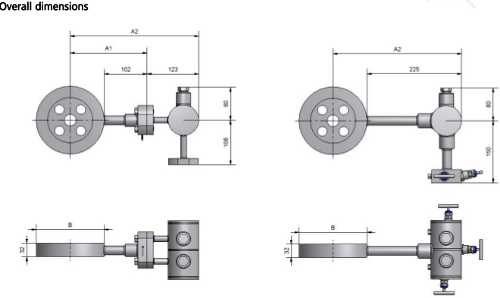
| Size | Pipe OD | Pressure rating | Inner pipe diameter | B | A1 | A2 |
|---|---|---|---|---|---|---|
| OD | rating | 54,5 | 107 | 156 | 279 | |
| DN 50 | 60,3 | PN 40 | 70,3 | 127 | 166 | 289 |
| DN 65 | 76,1 | PN 40 | 82,5 | 142 | 173 | 296 |
| DN 80 | 88,9 | PN 40 | 107,1 | 162 | 183 | 306 |
| DN 100 | 114,3 | PN 16 | 107,1 | 168 | 186 | 309 |
| DN 100 | 114,3 | PN 40 | 131,7 | 192 | 198 | 321 |
| DN 125 | 139,7 | PN 16 | 131,7 | 194 | 199 | 322 |
| DN 125 | 139,7 | PN 40 | 159,3 | 218 | 211 | 334 |
| DN 150 | 168,3 | PN 16 | 159,3 | 224 | 214 | 337 |
| DN 150 | 168,3 | PN 40 | 207,3 | 273 | 239 | 362 |
| DN 200 | 219,1 | PN 16 | 206,5 | 284 | 244 | 367 |
| DN 200 | 219,1 | PN 25 | 206,5 | 290 | 247 | 370 |
| DN 200 | 219,1 | PN 40 | 260,4 | 329 | 267 | 390 |
| DN 250 | 273 | PN 16 | 258,8 | 340 | 272 | 395 |
| DN 250 | 273 | PN 25 | 258,8 | 352 | 278 | 401 |
| DN 250 | 273 | PN 40 | 309,7 | 378 | 291 | 414 |
| DN 300 | 323,9 | PN 10 | 309,7 | 384 | 294 | 417 |
| DN 300 | 323,9 | PN 16 | 307,9 | 400 | 302 | 425 |
| DN 300 | 323,9 | PN 25 | 307,9 | 417 | 311 | 434 |
| DN 300 | 323,9 | PN 40 | 341,4 | 438 | 321 | 435 |
| DN 350 | 355,6 | PN 10 | 339,6 | 444 | 324 | 447 |
| DN 350 | 355,6 | PN 16 | 339,6 | 457 | 331 | 454 |
| DN 350 | 355,6 | PN 25 | 338,0 | 474 | 339 | 462 |
| DN 350 | 355,6 | PN 40 | 392,2 | 489 | 341 | 464 |
| DN 400 | 406,4 | PN 10 | 390,4 | 495 | 350 | 473 |
| DN 400 | 406,4 | PN 16 | 388,8 | 514 | 359 | 482 |
| DN 400 | 406,4 | PN 25 | 384,4 | 546 | 375 | 498 |
ANSI Flanges
| Size | Pipe OD | Pressure | Sch. 10S Inner pipe dia. | Sch. 40 Inner pipe dia. | Sch. 80 Inner pipe dia. | B | A1 | A2 |
|---|---|---|---|---|---|---|---|---|
| 2” | 60.3 | 150 lbs | 54,7 | 52,5 | 49,3 | 104,8 | 154 | 277 |
| 300 lbs | 111,1 | 158 | 281 | |||||
| 3” | 88.9 | 150 lbs | 82,8 | 77,9 | 73,7 | 136,5 | 170 | 293 |
| 300 lbs | 149,1 | 177 | 300 | |||||
| 4” | 114.3 | 150 lbs | 108,2 | 102,3 | 97,2 | 174,6 | 189 | 312 |
| 300 lbs | 181,1 | 193 | 316 | |||||
| 6” | 168.3 | 150 lbs | 161,5 | 154,1 | 146,3 | 222,3 | 213 | 336 |
| 300 lbs | 250,7 | 227 | 350 | |||||
| 8” | 219.1 | 150 lbs | 211,5 | 202,7 | 193,7 | 279,4 | 242 | 365 |
| 300 lbs | 308 | 256 | 379 | |||||
| 10” | 273 | 150 lbs | 264,6 | 254,5 | 242,8 | 339,7 | 272 | 395 |
| 300 lbs | 362 | 283 | 406 | |||||
| 12” | 323.9 | 150 lbs | 314,7 | 303,2 | 289,1 | 409,6 | 307 | 430 |
| 300 lbs | 422,3 | 313 | 436 | |||||
| 14” | 355.6 | 150 lbs | 346 | 333,3 | 317,5 | 450,9 | 327 | 450 |
| 300 lbs | 485,8 | 345 | 468 | |||||
| 16” | 150 lbs | 396,8 | 381 | 363,6 | 514,4 | 359 | 482 | |
| 300 lbs | 539,8 | 372 | 495 |
Overall Dimensions
Installation Requirements
The MHCOS flow meter can be mounted in a horizontal pipe. To maintain the 2% accuracy the minimum straight pipe run upstream shall be 2 x inner pipe diameter and 2 x downstream. Mass flow Mass flow measurement of saturated steam is obtainable with a multi variable pressure transmitter.
Typical Applications
Mass flow metering of saturated and superheated steam, with mass flow, temperature and pressure variables transmitted on 4-20mA and HART.
Works with:-
Differential pressure transmitters:-IDP10; IDP15; IDP25; IDP31; IDP50
And all our Absolute Pressure and Gauge Pressure transmitters, Temperature sensors and mass flow computers.
MultiVariable Transmitters :- IMV25, IMV30
If you require further information on this product or would like a quotation, please contact dp-flow on:
email: [email protected]
sales +44(0)1608 544222
Supplied by DP-Flow